2 years ago I developed a nasty infection in my sinus. It took 3 rounds of anti-biotics to finally rid myself of it. However, the damage it did left me with a peculiar situation. I can now hear my heartbeat in my left year. It comes and goes, more often when I have worked out a bit. Initially I found it annoying, especially when falling asleep but overtime I found it quite soothing especially when anxious. So I figured I could make a simple digital stethoscope for others to use as well. Something that you could carry with you easily. I've never worked with a purely analog circuit before so this would be a good way to learn about it.
- Feature List
- Design Breakdown
- Piezoelectric sensor
- Audio Amplifier
- Voltage Follower
- Decoupling Capacitors
- Output Jack
- Media
- Issues
- Future Scope
- Form factor should be as small as possible
- Power source should be easily rechargable/replaceable
- Both board and power source should be placed within a 3D printed container
- Power switch along with LED indicator to show if the device is on or not
- Adjustable volume control
- Adjustable base and amplification of audio amplifier
- Piezoelectric sensor should be inside a 3D printed dome to make it easy to hold
- Wire to piezoelectric sensor must be robust
Board Layout
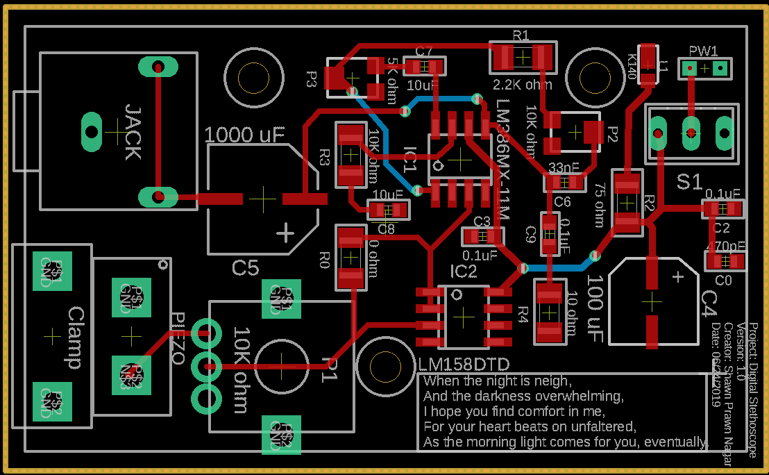
Schematic Layout
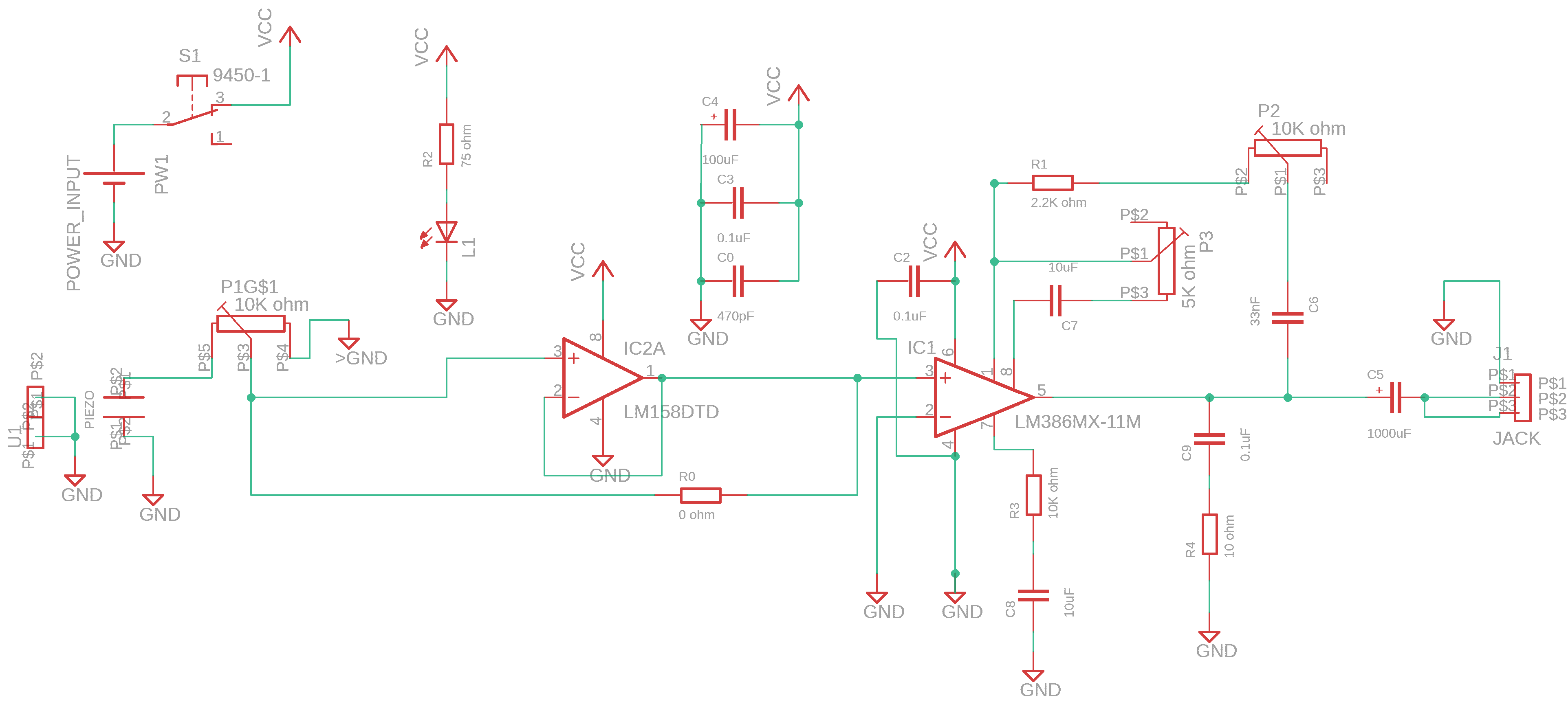
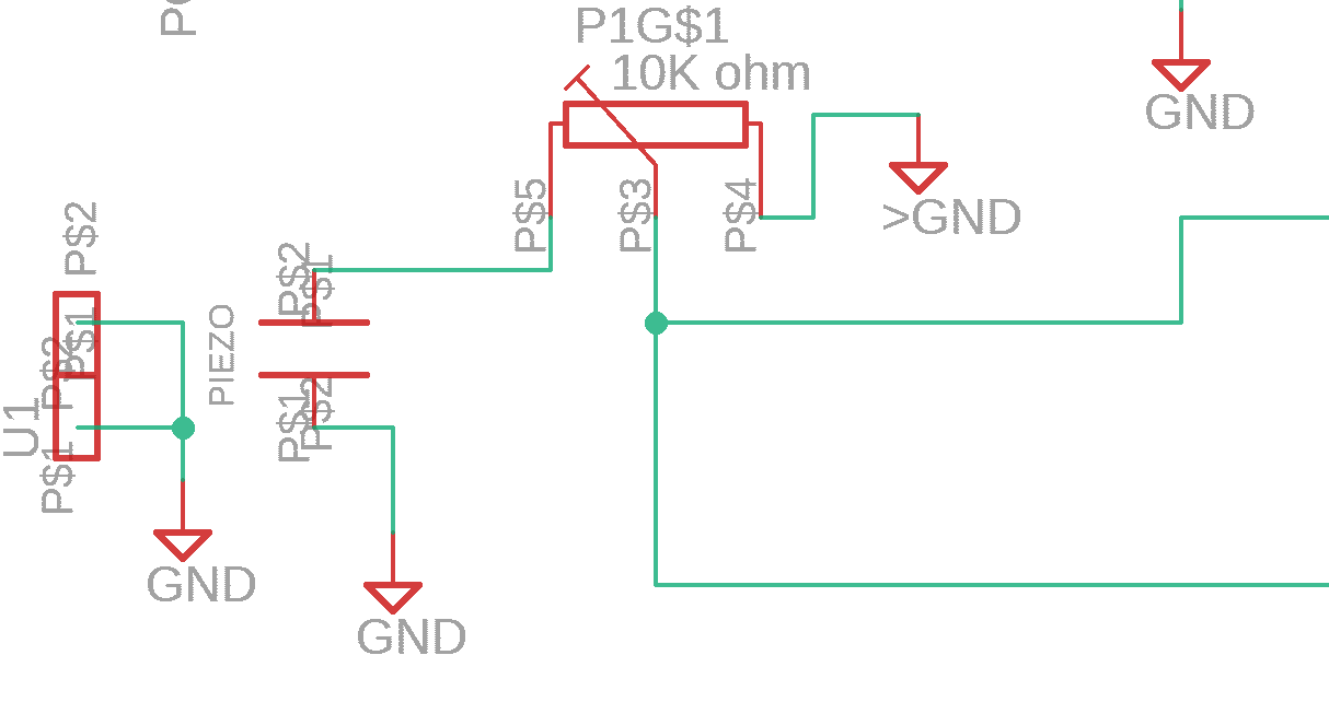
A piezoelectric sensor uses the piezoelectric effect to generate current at its terminals. Basically, when exposed to even the slightest mechanical stress, it generates a signal in proportion to the force on it. This makes it well suited as a surface placed microphone. I found that when I placed my device on a table, it could sometimes pickup conversations being had in the same room. The fact that it is incredibly thin and comes in various sizes makes it easy to build a simple case for as well.
I placed a 10k ohm potentiometer to attenuate the signal for volume control.
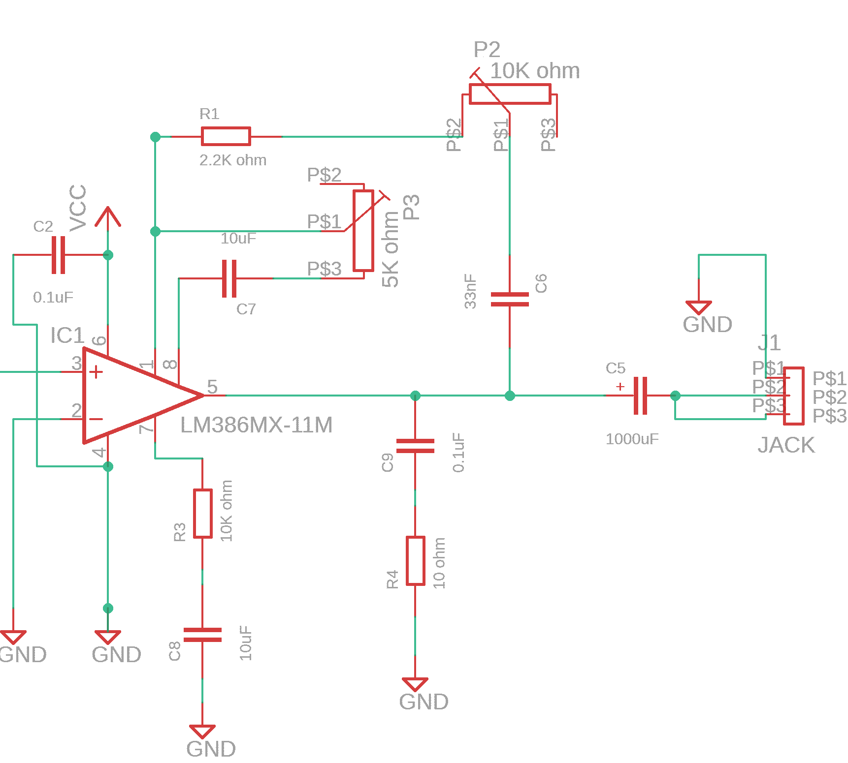 An audio amplifier is an opamp however the key difference being that it can drive far more current into low resistance loads like headphones. Basically it's output power is
a lot highter.
An audio amplifier is an opamp however the key difference being that it can drive far more current into low resistance loads like headphones. Basically it's output power is
a lot highter.
I used the LM386 low voltage audio amplifier. In fact, the reasons I used it was that it is very simple to interface and that there are countless hobbyist projects based on it. Another advantage is that it was built for low power battery operated devices.
By adjusting external resistors at certain pins, you can change the gain as well as introduce a kind of base boost. The circuit example my design is based on is given in the typical application section of the datasheet [Section 9.2.5]. I used a 5k and 10k ohm potentiometers for amplifier and base boost control.
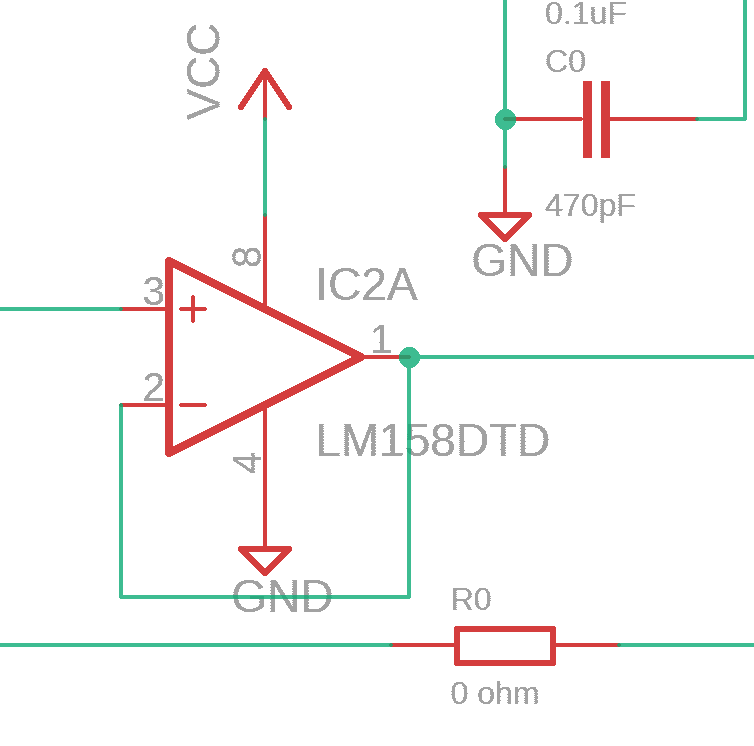
A voltage follower is an opamp circuit that is used to act as a buffer between 2 sections of a circuit to isolate them from one another. It is also known as a unity gain amplifier because its gain is 1. Thus the voltage signal at the input is replecated at the output.
My reasoning for using this was that I didn't want changes in impedance or capacitance at the Piezeoelectric sensors end to affect that audio amplifier.
I chose theLM158 mostly because it was lying around. At the time I figured it might not work so just in case I placed a pad for a 0 ohm resistor between the output of sensor and input of the audio amplifier, thus avoiding the voltage follower completely. I deliberately chose to make a voltage follower instead of using a buffer IC out of curiosity.
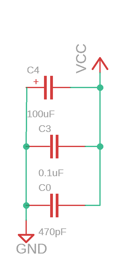
With any circuit, decoupling and by-pass capacitors are essential to smoothen out noisy signals are shunt away the noise. My biggest concern was noise from the power supply, espeically as the battery got more discharged. So I placed 3 capacitors near the power supply. 100uf filters low frequency noise, 0.1uf filters high frequency noise and 0.47 uf for good measure.
At every power pin on each IC, I placed 0.1uf capacitor. The closer the capacitor to the pin, the better.
The output jack is a standard 3.5mm female header for your every day headphones. The circuit only serves mono so I shorted the L and R pins.
Soldering SMD components
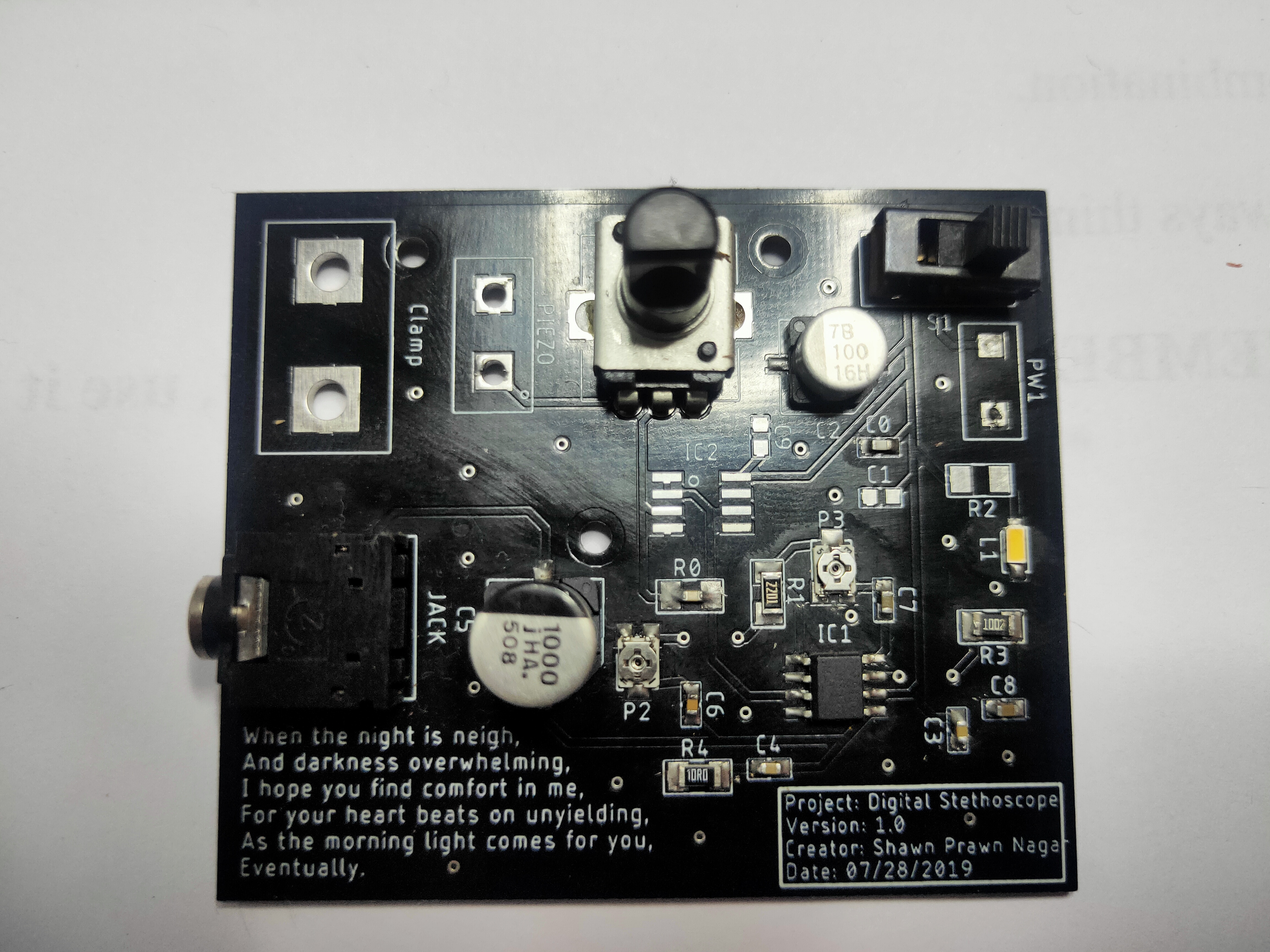
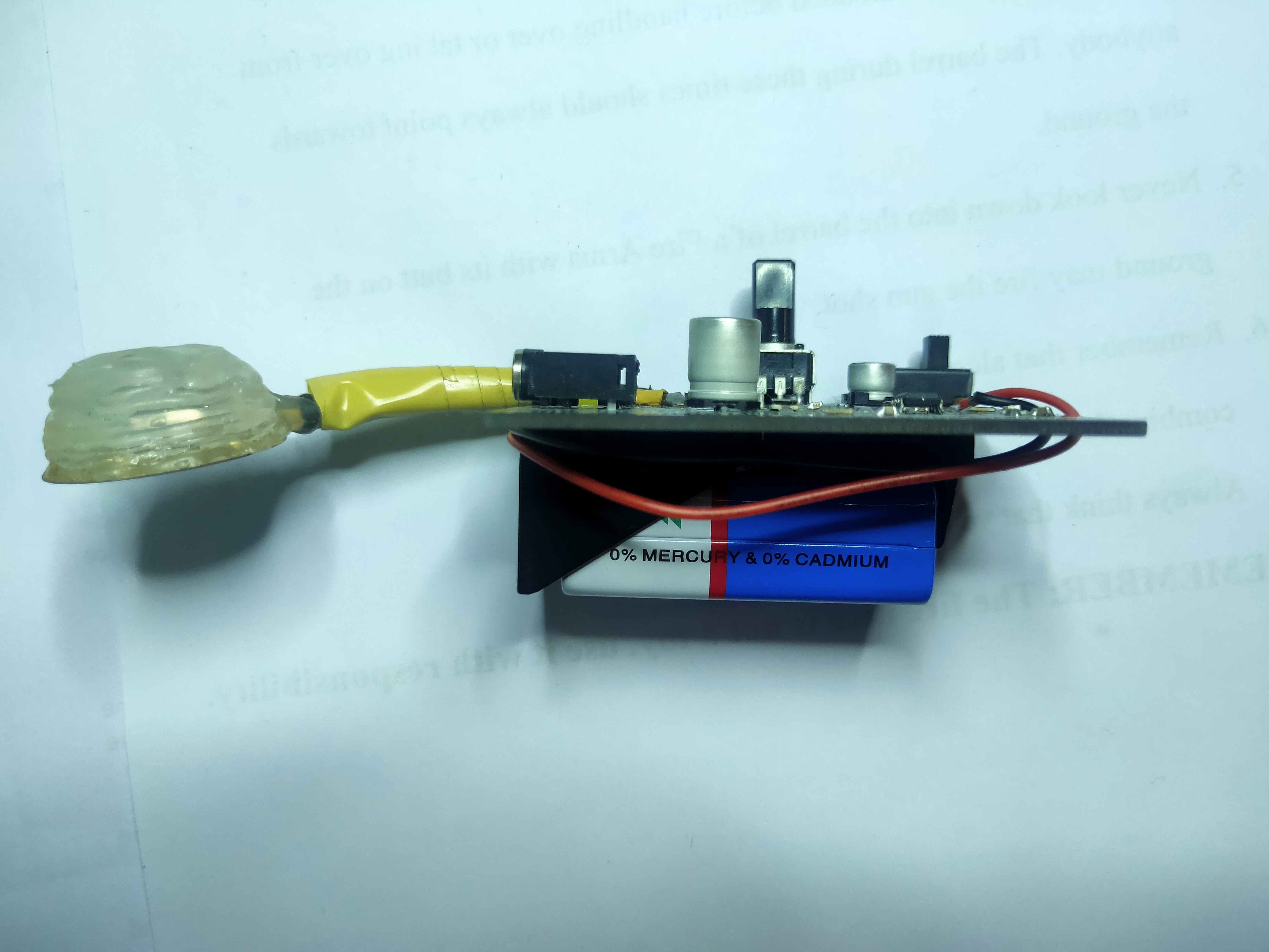
Working Protoype [Front]
Note: I made a dome shaped handle for the piezoelectric sensor out of hot glue. Eventually I chose not to 3D print the handle as I abandoned this version of the project
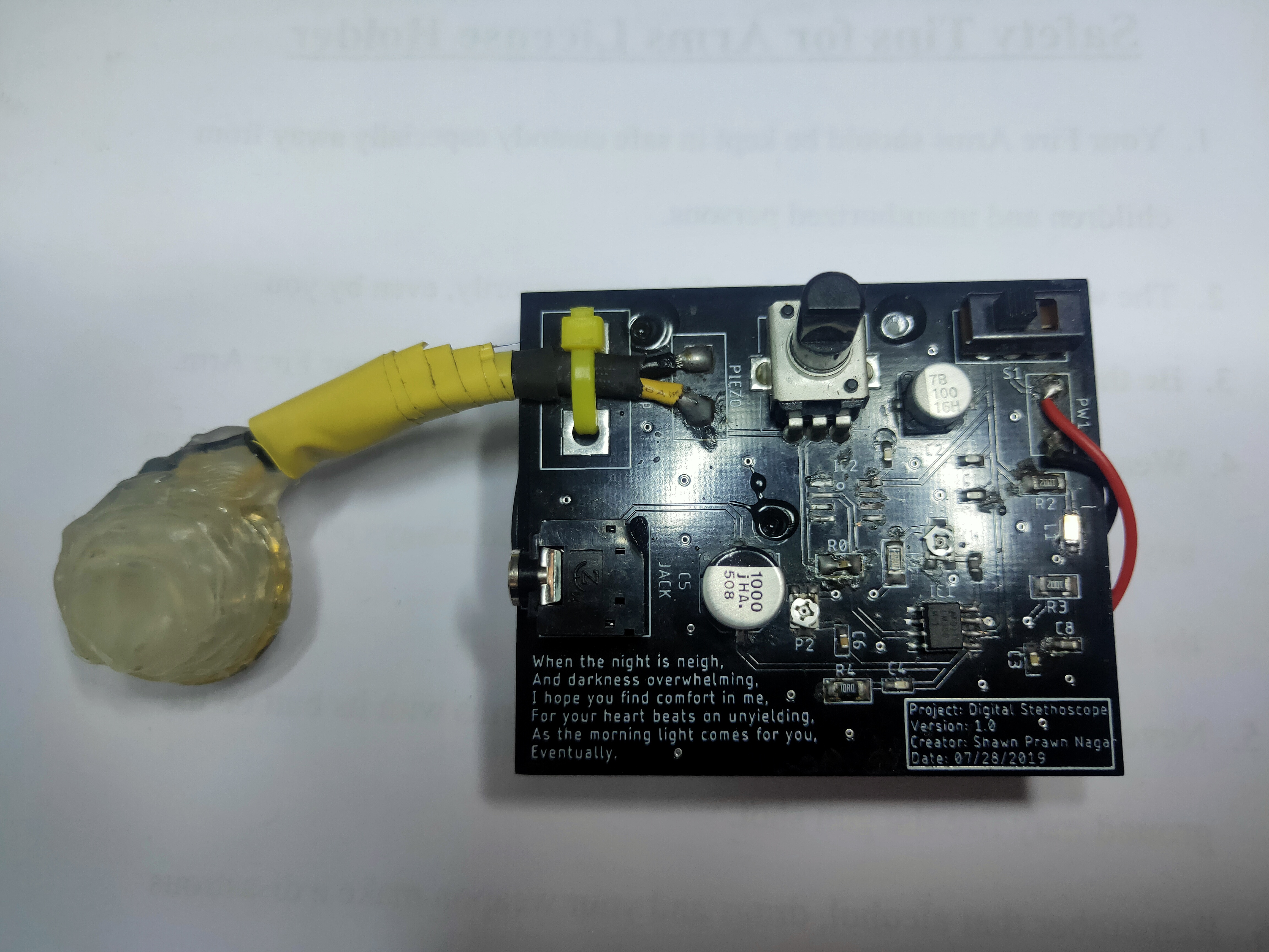
Working Protoype [Side]
The problem with analog circuits is that testing on a breadboard is very difficult. Noise, loose connections etc make getting any reasonable performance difficult. I did build this circuit on a zero board but even that was susceptible to Noise. I placed some insulation on the soldered joints but the performance was still mediocre. I made the decision to go ahead and test the design on an actual PCB. Here is what I encountered:
- The 9V battery is quite cumbersome to use. It's large and bulky and designing a case for a removable battery is much harder than to have an internal battery with a simple micro-usb charging port instead.
- When using the voltage follower no signal would make it to the audio amplifier. I believe this is because the Minimum Input Current required by the opamp was too high compared to the signal being given by the Piezoelectric sensor. I suspect because the current output from the piezoelectric sensor is so low (in the range uA).
- Another issue was a significant voltage drop across the thick wires I used to connect the piezoelectric sensor to the circuit board. Ofcourse length is a factor. The wire also acted as an antenna which just worsened the noise.
- The maximum volume in my headphones was too low. I would have to hold the headphones against my ear to hear something. This is because I didn't implement a pre-amplifier opamp before the audio amplifier.
I have plans for a version 2.0 of this project. Thats the reason I decided not to spend time and money on 3D printing a case.
- Instead of a replaceable 9V battery, I intend to use a re-chargeable lithium ion battery with a simple micro-usb connector. This will require some kind of BMS( Battery Management System) IC.
- Active filters. I have been looking into several low pass filters and settled on 3rd order butterworth filter with -3db cutoff at 100hz. I good resource for filter design can be found here. These will filter out all other audio except for low frequency signals which makes sense since a heart beat signal will be less than 100Hz in frequency.
- I will implement a pre-aimplifier at the input of the audio amplifier. This should solve the issue of low volume at the headphones.
- I will attempt to place the piezoelectric sensor directly on the 3D printed container so as to reduce the length of the wire considerably and improve form factor.
- I want to learn how to simulate circuits as well as avoid real world noise and interference during testing. So before I make any move, I will simulate a low frequency sinosoidal on my circuit and design and see how it performs. LTspice is what I am thinking of learning.
Thats the plan so far. Look out for a version 2.0 soon!
Also for those interested, I found an excellent resource for a circuit similar to this here.