
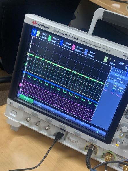
Image right: 12-bit word 111111000000 with start and stop bits 1,0 is serialized and sent out in LVDS format (original and inverted copy) out of the two cables attached to little brown square on the top left corner. (No other encoding). It is recovered by the deserializer (pictured above; small purple square on top edge) with its start and stop bits stripped away. The result (1111100000) is displayed in hexadecimal on the DE-10 Lite FPGA.
Image left: 10 MHz clock (in pink) and oscillating bits of word 101010101010 recovered by deserializer.
Pin assignments, board specifications, and other project config details sit in the .qsf file. The .qsf file assumes the deserializer is external hardware, and simply sends out the serialized word bit by bit at 10 MHz.
The top-level module (top.v) contains:
- A phase-locked loop that adapts the 50 MHz DE-10 Lite clock to 120 MHz;
- A pseudorandom bit generator (the LFSR), in the "modulator" module, which sends out a random bit every clock (modeling 120 MBps data stream);
- A word generator, packaged into the modulator, which takes in the random bits and packages them together as 12-bit words (10 MHz output stream);
- A modulator, which sends out serialized data using a submodule, xor_word;
- A module linking to the board LEDs to display the output of an external deserializer (written by Greig Scott).*
The final module should ensure the DE-10 Lite FPGA displays whichever word is being written out of word_generator.v. To test, I used 12'b101010101010 (oscillation) and 12'b111111000000 (square wave). If word_generator is configured to use the output of the LFSR, the FPGA lights up with a static [reverse-b]88, since it displays in hexadecimal, and since the data output is too fast for the human eye to resolve (although a spectrum analyzer/oscilloscope will show it is perfectly random). The first digit zips between 1, 2 and 3, while the other two are unbounded and free to cycle through all possible numbers.
LFSR details:
Written with reference to Patrick Schaumont's lecture http://rdsl.csit-sun.pub.ro/docs/PROIECTARE%20cu%20FPGA%20CURS/lecture6[1].pdf
Modulator details:
This module hooks up the word generator output to an xor_word module. This module does NOT actually XOR anything. Its name is just shared with the other DPSK project on this account. Amplitude-shift keying does not involve any XOR'ing; the modulator just sends out the original word, unaltered, bit by bit.
*Note that the top-level module has "demodulated" and a "neg_demodulated" outputs. This implements LVDS, which acts as if the original signal has been split and one stream of it inverted. This is because our deserializer hardware (TI SN65LV1224 "10-MHz To 66-MHz, 10:1 LVDS SERIALIZER/DESERIALIZER") expects such input. The outputs are called "demodulated" even though they're actually not just because I named them like that, and they stayed this way. They are not demodulated. They are not even modulated. They are exactly the same bits as the raw word being written in, split into LVDS format (meaning one of them is the original word bit, and the other is inverted).
This deserializer takes in a 10 MHz reference clock (which I supplied with an arbitrary function generator) to recover the clock and the data. If it is unable to phase lock, try switching the ports that take in the "demodulated" and "neg_demodulated" outputs.