hardware design files and software applications for an esp32c3 + 200 "smart LEDs" project.
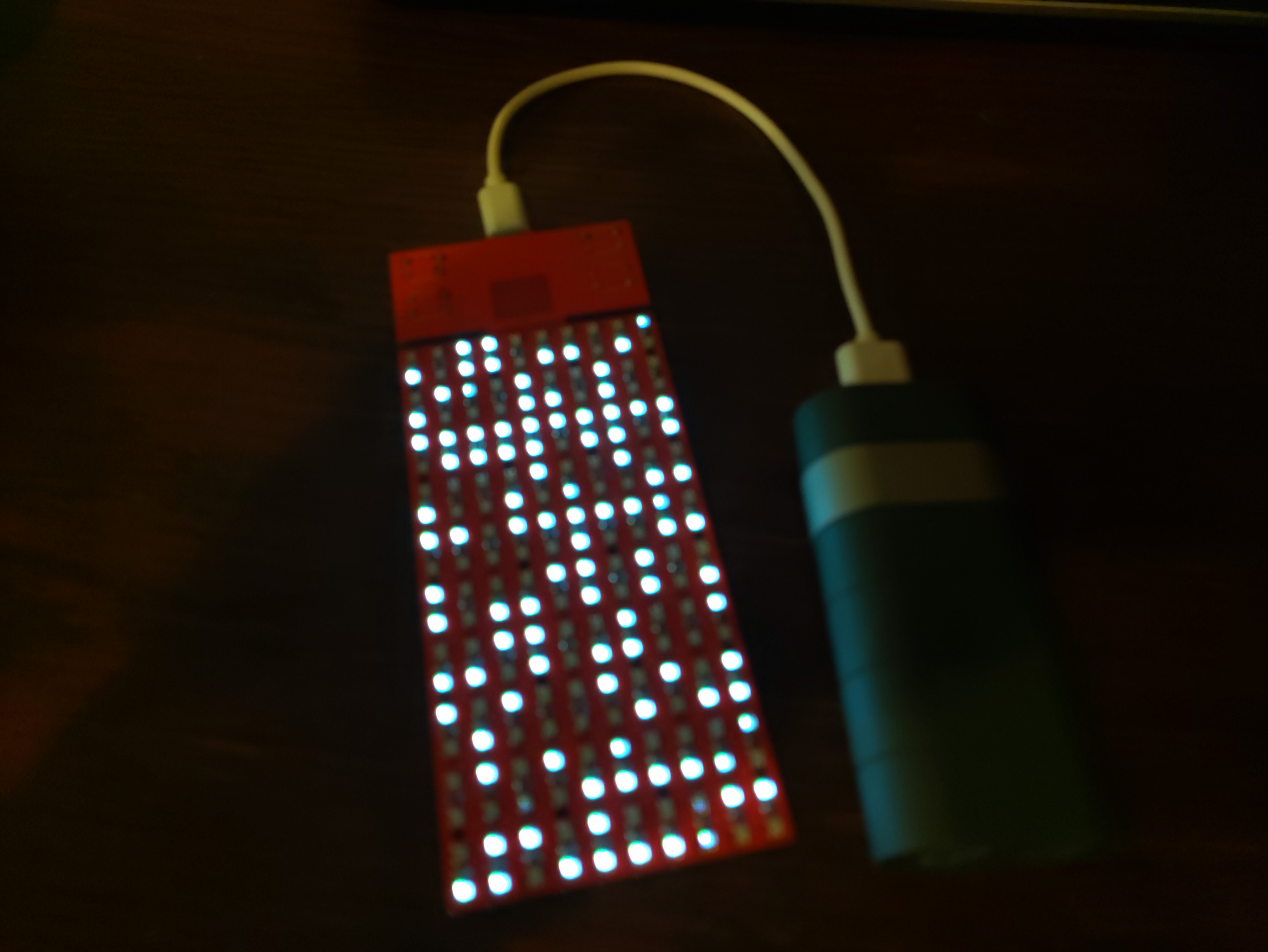
The PCB contains an ESP32-C3, 4 buttons and 200 ws2812B-like "smart LED" components that each contain three 256 level PWM controllers to drive the Red, Green and Blue LED channels. This means that each LED can theoretically display 2^24 colour combinations. The LEDs are supplied with the necessary data using a serial protocol, and are all connected in series in a single "string", so to drive all the LEDs, the ESP32-C3 must send 200 * 24 = 4800 bits of data. The LEDs need this data to be supplied at a net rate of 800,000 bits per second. The actual low-level protocol used to transmit the data to the LEDs is as follows:
- ALL bits for a string of LEDs must be transmitted as a continuous stream immediately after a "reset pulse"
- A "0"-bit is transmitted as a 4 us high level, followed by an 8 us low level
- A "1"-bit is transmitted as an 8 us high level, followed by a 4 us low level
- After all bits have been transmitted, a 50 us low level serves as a "reset pulse"
This could be done using "bit-banging", but then the ESP can do little else aside. Alternatively, one can put one of the ESP32-C3's hardware peripherals to "alternative use".
The "hardware" folder contains the schematic diagram and KiCAD source files for this project.
PLEASE NOTE THE FOLLOWING:
This Do-It-Yourself project comes without any guarantee whatsoever.
5V Power should always be supplied to the LED portion DIRECTLY, NOT via the USB connector on the ESP32-C3 module.
It is, however, possible to supply the ESP32-C3 from the LED portion power supply by fitting a 0 Ohm resistor to R2. R2 should ONLY be fitted if you want to power the ESP32-C3 from the power supply connected to the LED portion, and it is then recommended to completely disconnect the USB cable and remove the USB connector from the ESP32-C3 module to prevent accidentally drawing power for the LED portion through the USB cable connected to the ESP32-C3 module.
Attempting to supply power through the USB connecter to the ESP32-C3 AND the LED portion may lead to damage to the ESP32-C3 module AND/OR to the USB power source. The LED portion alone can draw in excess of 1.5 A, and the ESP32-C3 module PCB traces and components are NOT rated for this. The LED portion does NOT properly negotiate its power draw with the power source by itself, and while the ESP32-C3 might be able to take on this task, there is no guarantee (given that users can run their own code on the ESP32-C3) that it will.
TL;DR: Do not fit R2 unless you know what you are doing and willing to bear any and all consequences.
The "software" folder contains some self-contained example Arduino applications. Two of these applications demonstrate the use of ESP32-C3's hardware peripherals to drive the display .
The ledscreentest1 example demonstrates the use of the "RMT" perhipheral.Can generate very accurately timed signals, but has enormous memory overhead: it requires 32 times more storage than there is raw data to be sent to the LEDs. 24 bits to be sent to each LED requires 768 bits of memory. Every RGB byte translates to 8 32 bit word accesses. This method uses DMA (Direct memory access) to relieve the processor of these duties: The processor just needs to prepare a block of data and then start the transfer.
The ledscreentest2 example demionstrates the use of the "SPI" perhipheral. Signals are less accuratly timed, but do actually work with the types of LEDs tested so far. Overhead is much lower than for the "RMT" method: it requires 4 times more storage than there is raw data to be sent to the LEDs. 24 bits to be sent to each LED requires 96 bits of memory. Moreover, as every (RGB) byte access becomes a single 32 bit word access, processor overhead is relatively limited. This method uses DMA (Direct memory access) to relieve the processor of these duties: The processor just needs to prepare a block of data and then start the transfer.
The blocktris example game uses 6 combinations of 2 buttons that are simultaneously pressed to control a falling block:
- start game
- move left
- move right
- turn clockwise
- turn counter-clockwise
- drop
Objective of the game is to score points by completely filling as many rows on the board as possible: 1 row = 1 point, 2 rows = 4 points, 3 rows = 9 points and 4 rows = 16 points. Completed rows are removed from the board, and the game ends when there is no more room for a new piece to spawn.
If you fill in the login credentials of an access point, the module will try to communicate a (global) high-score with a server.
Fly a brick, avoiding increasingly difficult obstacles along it's path by commanding it to flop using the "flop" button.
As Espressif regulary makes breaking changes to their API, it is important that you use the correct version of the Espressif framework for Arduino: 3.1.3
After you have installed the Espressif board manager package, you can select the "ESP32-C3 Dev-module", which is compatible with the ESP32-C3 "super-mini" module that is usedin this project.
Please make sure that you have set the option "USB CDC enable on boot" to "enabled" (Arduino tools menu), and that you have selected the correct serial device.
