Tutorials
The section gives brief description of tutorials from the tutorials directory. Tutorials are sorted into sub-directories according to solvers.
Warning: the tutorials are not updated regularly and therefore it may happen that some setup will be out-of date. Next, the repository uses several branches, so the case can be relevant to different branch.
This tutorial shows the setup for 2D inviscid transonic flows through a channel with a circular arc bump at the lower wall.
The length of the channel is L = 3m and the height is H = 1m. There is a 1m long circular arc bump at the lower wall located 1m from the channel inlet. The height of the bump is h = 0.1m.
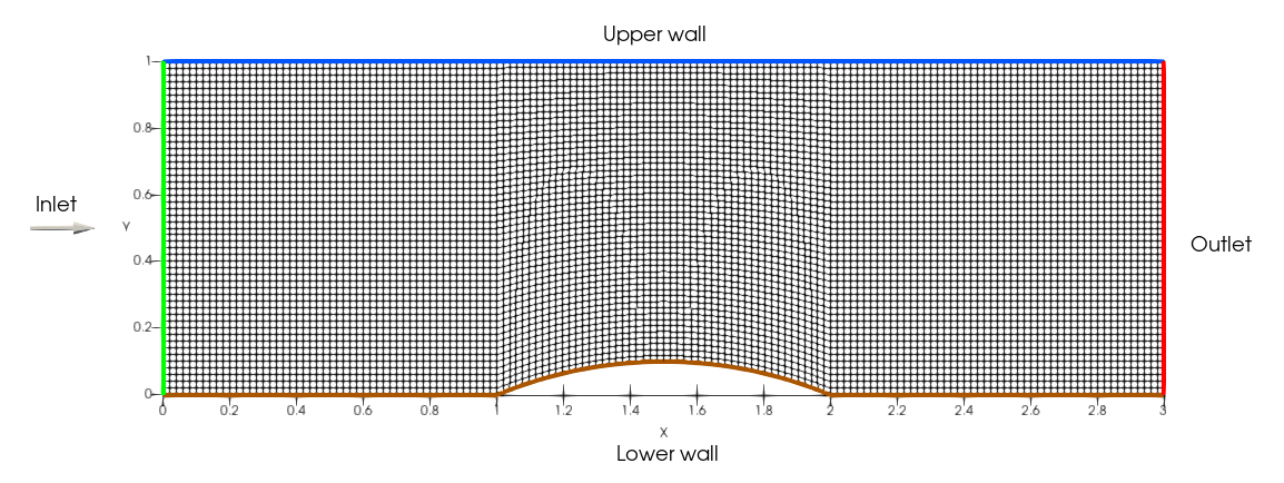
The case uses structured mesh with 150x50 quadrilateral cells created with blockMesh (see system/blockMeshDict).
The flow is considered as inviscid with the equation of state for perfect gas. The boundary conditions are:
- inlet: given total pressure p0 = 100 kPa, total temperature T0 = 288.15, and flow direction
$dir$ = (1, 0). - outlet: given static pressure p2 = 73.7 kPa
- walls: non-permeable slip condition
The computation setup in openFOAM is therefore:
- p:
totalPressureat the inlet,fixedValueat the outlet,zeroGradientat walls - T:
totalTemperatureat the inlet,zeroGradientat the outlet and walls - U:
subsonicInletTotalat the inlet,zeroGradientat the outlet,slipat walls
Notes:
- the
pressureInletVelocityand its variants are not compatible withmyLusgsFoamsolver! Therefore thesubsonicInletTotalshould be used for velocity. It calculates the inlet velocity magnitude using Riemann invariants. The condition is compatible only with perfect gas EOS! - the realGas branch of repository contains specific set of inlet/outlet boundary conditions.
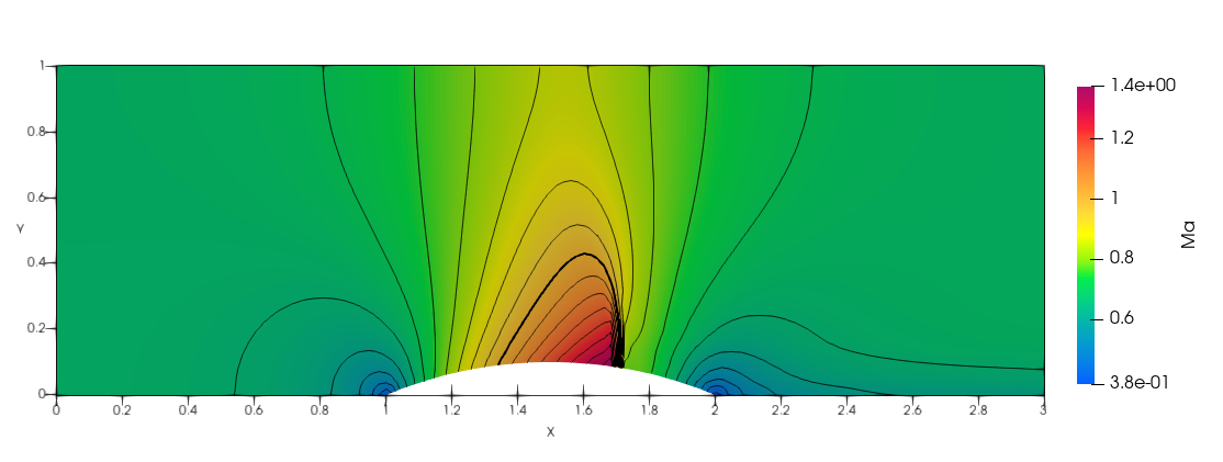
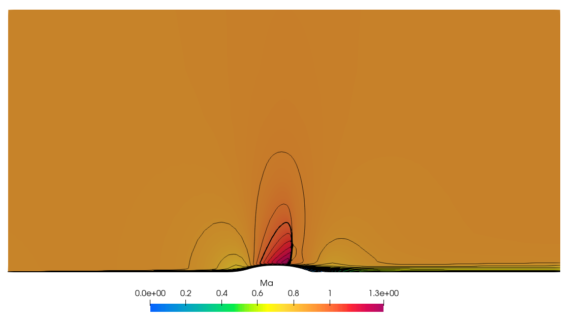
The following image shows the distribution of Mach number in the channel. One can see a shock wave at the bump (at x approx. 1.7). The thick line is the sonic line (i.e. Ma = 1).
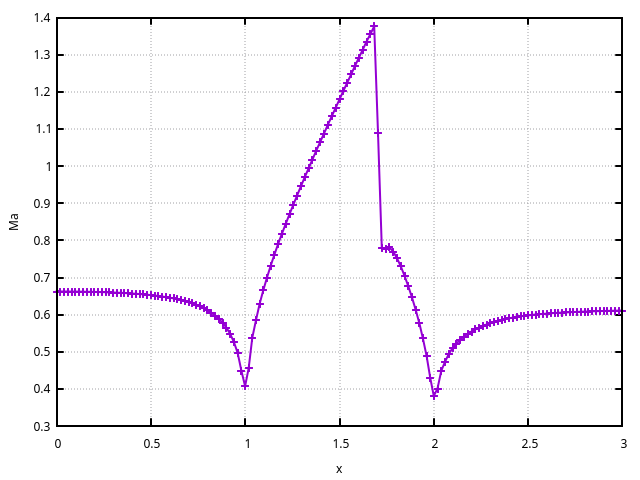
The distribution of Mach number along the lower wall is extracted using standard postprocessing tools. It can be found in postProcessing/surfaces/20000/Ma_lowerWall.raw. Plot column 4 (Mach number) versus column 1 (x coordinate)
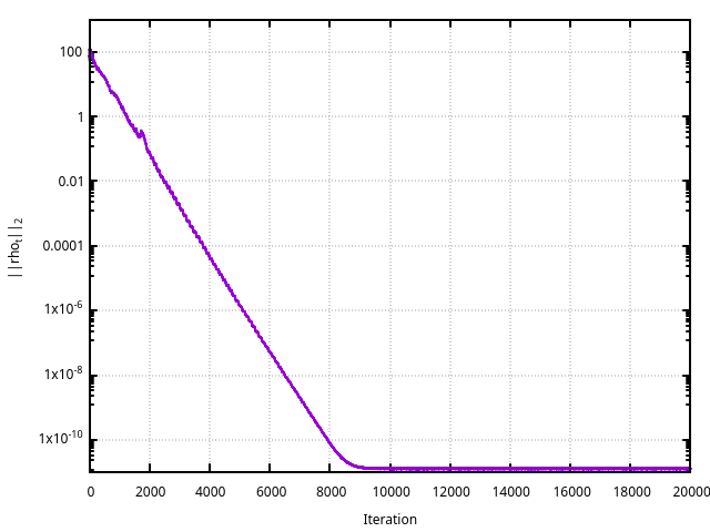
The convergence history can be extracted from the log file using foamLog log.myLusgsFoam.
This tutorial shows the setup for 2D inviscid low Mach number flows through a channel with a circular arc bump at the lower wall. The case uses the same geometry, mesh, and boundary condition setup as the transonicChannel case. The differences are in the value of outlet pressure and in the numerical flux.
This is the axisymmetric transonic bump case from the NASA validation page. The description of the case can be found
here.
The setup more less corresponds to transonicChannel. The difference is that a no-slip boundary condition is assumed at the lower wall. Moreover, the flow is viscous and the turbulence is modeled with a two-equation k-omega SST turbulence model.
To run the tutorial, one has to run getMesh.sh at first. It downloads the mesh from NASA site and then it converts the mesh to OpenFOAM format. Then the calculation can be performed with Allrun script.
2D inviscid hypersonic flow through over a cylinder - ...
2D flow through ERCOFTAC pump, MRF approach - ...
2D flow through ERCOFTAC pump, dynamic mesh approach - ...