
This project features a wheeled excavator arm that utilizes a synchronized system of pistons and mechanical linkages to translate linear movement into precise lifting and scooping actions.
- The system operates with three independent degrees of freedom: the Boom for vertical lift, the Dipper for reach extension, and the Bucket for material handling, closely replicating the fluid motion of a real-world excavator.
- By adjusting the linear actuators, the assembly dynamically changes its geometry. The dual Boom Pistons at the base control the vertical elevation of the entire arm, while the specialized DogBone and HLink mechanism translates the linear push of the upper Bucket Piston into a wide, precise rotational scooping range for the bucket.
- The strategic placement of parallel pistons at the Boom base and integrated pivot bars maximizes structural leverage. This setup multiplies the actuator force, ensuring high stability and load distribution across the entire arm assembly.
- The entire arm mechanism is integrated onto a compact 4-wheel mobile chassis, transforming the standalone arm into a fully functional and mobile industrial vehicle model.
- The structural connection points are optimized for real-world manufacturing. The linkage bars and pivot joints use custom-engineered Snap-Fit mechanisms, featuring calculated mechanical tolerances between the entry slots and the pins. This allows the parts to snap together securely during assembly while maintaining smooth, non-sliding rotation during operation.
This excavator arm features a synchronized joint system that accurately replicates real-world machinery. At the core of the design is the Station , a custom curved hub that connects the Boom, lower cylinders, and wheeled chassis together. By linking these main parts in one spot, it maximizes structural stability and keeps the entire base steady during lifting.
The assembly operates smoothly using precisely calibrated Revolute and Slider joints. To keep the movement efficient, the upper Bucket Piston does not drive the Bucket directly. A direct connection would cause the piston to line up straight with the bucket's pivot point at full extension, pushing directly into the solid axis and locking the mechanism in a dead angle. Instead, the piston drives the DogBone and HLink assembly. This intermediate linkage constantly shifts the direction of the force, smoothly converting linear push into a wide, powerful scooping motion. This setup allows the bucket to rotate fully without ever getting stuck.
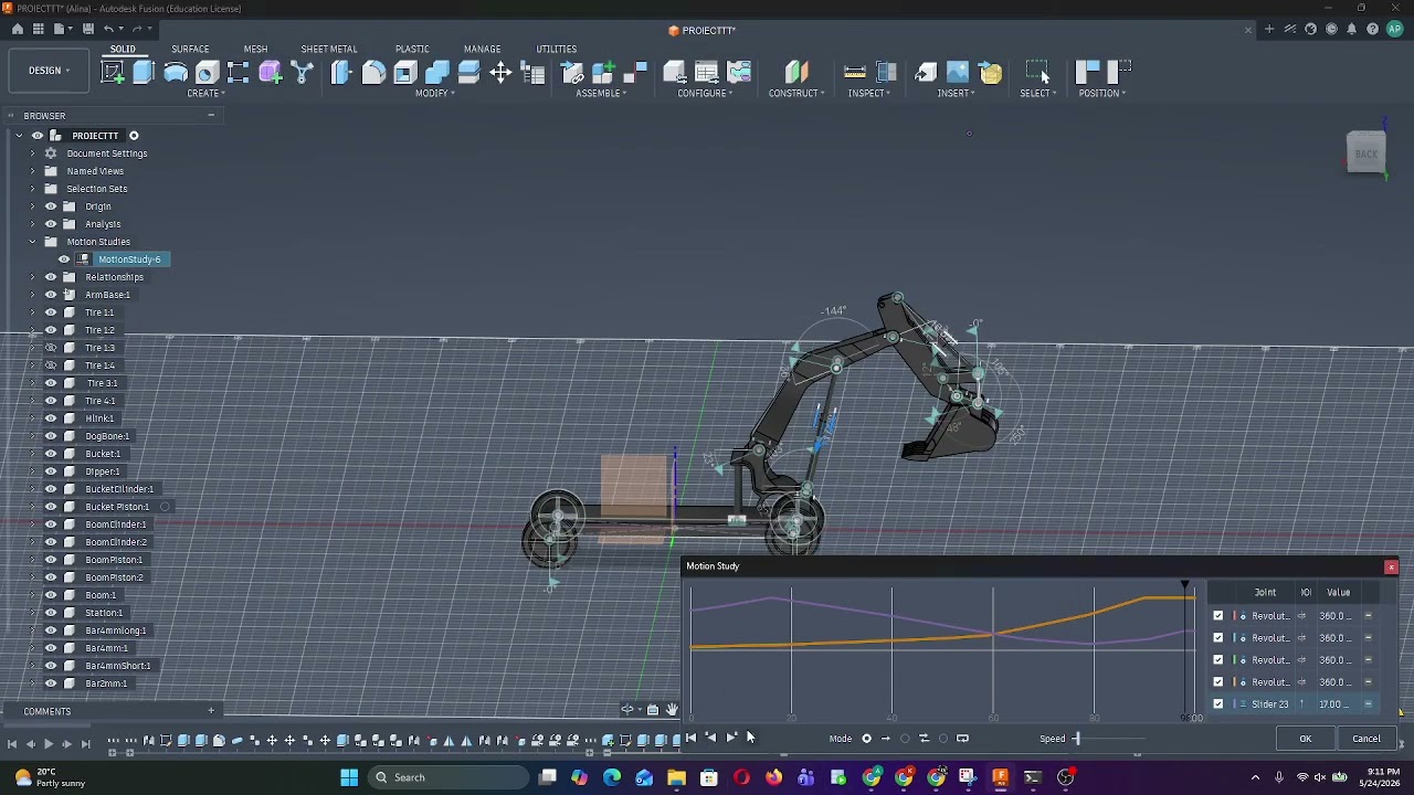
| Component | Description |
|---|---|
| Boom | The heavy-duty primary arm segment that handles the main vertical lifting and elevation of the system. |
| Dipper | The secondary structural arm segment that extends the reach of the machine. |
| Bucket | The end-effector designed for digging, scooping, or grabbing materials. |
| Boom Cylinders & Pistons | TThe dual linear actuator assemblies (cylinders and internal pistons) mounted at the base to drive the lifting of the Boom. |
| Bucket Cylinder & Piston | The upper linear actuator assembly that controls the rotation and tipping angle of the bucket. |
| Arm Base | The main support platform that holds the weight of the arm and serves as the primary anchor point. |
| Tires | The tires of the arm based so that the excavator could move. |
| Station | The curved structural mount located at the base of the arm; it serves as the primary anchor connecting the Boom, the lower cylinders, and the main chassis(ArmBase) platform together. |
| DogBone & HLink | The main support platform that holds the weight of the arm and serves as the primary anchor point. |
| Linkage Bars (Bar4mmLong, Bar4mm, Bar4mmShort, Bar2mm) | A set of precision connecting bars of various lengths that synchronize joint movement and stabilize the bucket linkage. |
A: You have two options depending on what you want to do:
- The Full Experience: You can download the complete PROIECTtt.f3d file to open the entire assembly, components, and Motion Study in Autodesk Fusion 360.
- Component-by-Component: If you only want to inspect, modify, or 3D print specific parts, you can download the separate .f3d or .stl or .gcode files for each individual component, like the Station, Boom, or Bucket.
A: The biggest headache was getting the exact proportions right. If a component like the Dipper or Bucket is off by even 2mm, the cylinders won't reach their mounting points or the whole mechanism locks up. It took a lot of attention to detail and on-the-fly adjustments to make sure every single piece cleared the chassis and moved properly.
A: Short answer, YES. Setting up the joints in Fusion 360 was the perfect way to test my anger management. Managing multiple Revolute and Slider joints at the same time usually meant that if I fixed one alignment, three others would break. The absolute worst part was definitely the Bucket Slider joint, if that linear movement wasn't aligned down to the exact millimeter with the rest of the linkages, the whole arm would just lock up and refuse to move entirely.
A: Initially, no, it wasn't. I realized way later that I can't just connect a cylinder to another part using a perfect closed circle, because you wouldn’t be able to physically assemble it. To fix this, I literally cut the connectors on the Bucket Piston and HLink into a "U-shape" with proper mechanical clearance so they can actually slide onto the pins.
A: The biggest takeaway was definitely learning how to design for the real world, not just for the screen. It’s easy to make parts look good in CAD, but this project forced me to think about assembly and physics. I learned that you always have to leave mechanical clearances (tolerances) for moving parts, and that you need to plan how a human will actually snap the pieces together at the end. It completely changed how I look at mechanical objects now.
I also had to downsize some specific pieces, like the DogBone where it connects into the Dipper. Originally, there was no way to physically insert it because the parts wouldn't bend that much during assembly. Making that piece slightly smaller gave it the exact room it needed to fit into place perfectly.
A: The biggest takeaway was definitely learning how to design for the real world, not just for the screen. It’s easy to make parts look good in Fusion, but this project forced me to think about assembly and physics. I learned that you always have to leave tolerances for moving parts, and that you need to plan how a human will actually snap the pieces together at the end. It completely changed how I look at mechanical objects now.