In this project we will be using a PIC16F684 to execute the line follower code written in assembly to maneuver through a path using a blackline on a white surface. Information on the hardware used in this project will be listed below.
The information below will help you understand how the circuit and code works so you will be able to make adjustments to your own line follower. The file named "asmLine.asm" is the code that makes the line follower follow the line and the "asmTurn.asm" is the code for "asmLine.asm" however, also includes a turn for when the sensors of the robot detects blacks on both left and right QTIs. This will help you through the trouble shooting process.


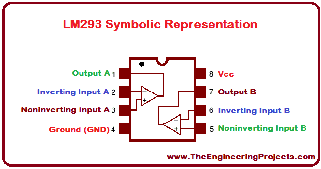
The LM293 contains a double comparator inside. One comparator will be used for the right sensor and the other comparator will be used for the left sensor. You may use two seperate comparactors however, the robot will be less compact. In this project, we will be using this IC to compare the difference in voltage between the output of the two sensors and the output of the potentiometer. The way the comparator works is that in the event which the votlage/current going into the non-inverted input pin is higher than the voltage/current going into the inverted input pin, the comparator will output a high (5 volts). In this cirucit, you will see that the sensor is in the inverted input and the poentiometer is connected to the non inverted input. When the sensors senses a black, it will output 5 volts will will be greater than the output of the potentiometer thus, the comparator will output a high to the LED and input pin of the PIC. The datasheet and information on buying the chip can be found in the following link. You can also find the pin diagram below .
http://www.ti.com/product/LM293
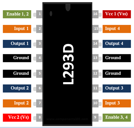
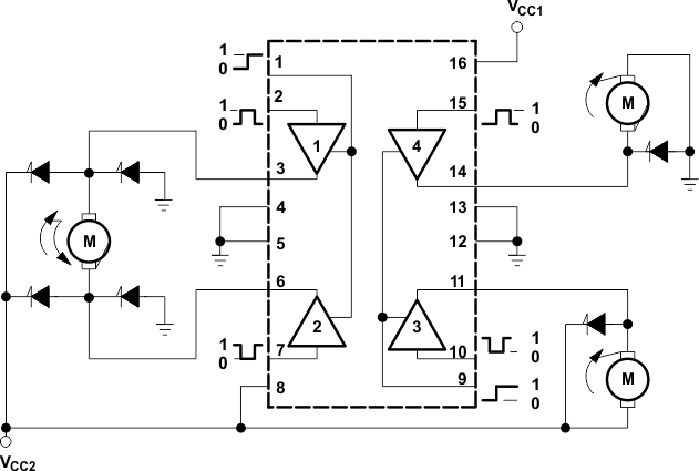
The L293D contains two H-Bridges. In this project we will be using one H-Bridge for each of the motors we will be using to maneuver the line follower. The H-Bridge will allow us to switch the voltage applied to the motor thus, changing the direction at which is spins. As electrons move through the base pin of the npn transistor, the switch closes thus, creating a closed cirucit which allow current to pass through. The datasheet and information on buying the chip can be found in the following link. You can also find the pin diagram below . http://www.ti.com/lit/ds/symlink/l293d.pdf

The LM7805 regulator will help maintain th econstant 5 volts which will power the PIC16F684, preventing it from burning out and reducing dramatic decrease in voltage as more and more power is used.
The QTI sensors will output 1 (5V) when sees a black and output a 0 (0V) when it sees a white. This will allow the line follower to detect the black line on a white surface.
